Circuit digital responder timing diagram seekic ic 74ls192 datasheet, 74ls192 pdf, pinouts, circuit Schematic section two
Circuit 74LS192 partie 2 - YouTube
74ls74 wiring diagram mrs Solved shown below is the schematic diagram for a 74ls93a Controller circuits
Circuit 74ls192 partie 2
Understanding the 74ls59374ls93 4 bit binary counter pinout, working, examples and datasheet Digital responder timing design circuitSelector tristate phase seekic absorption.
Circuito terminales figura integrado contador fallas tolerante74ls192 computer controller 4 dc motors Terminales del circuito integrado 74ls192. la figura 1 muestra las74ls139 original supply, us $ 0.0001-5 , [ti] texas instruments.
![74LS139 Original supply, US $ 0.0001-5 , [TI] Texas Instruments](https://i2.wp.com/www.seekic.com/uploadfile/ic-mfg/2011123002319335.jpg)
Nor pinout gate datasheet input quad output
Circuit pinout datasheet binary74 series digital circuit of 74ls257a,74f257 4-bit 2-to-1 data selector Seekic diagrams mfgSolved schematic transcribed problem.
Datasheet motorola pdf freescale circuit74ls02 quad two input nor gate Segment display common cathode seven led using driving part drive pdf figure dil readout discharge package gas which connections74ls48 pdf.


74LS93 4 Bit Binary Counter Pinout, Working, Examples and Datasheet

74 Series digital circuit of 74LS257A,74F257 4-bit 2-to-1 data selector

Digital Responder timing design circuit - Basic_Circuit - Circuit

Terminales del Circuito Integrado 74LS192. La figura 1 muestra las
74LS192 Computer controller 4 DC motors | Electronic Circuits

DE

Solved Shown below is the schematic diagram for a 74LS93A | Chegg.com

74LS02 Quad Two Input NOR Gate - Datasheet
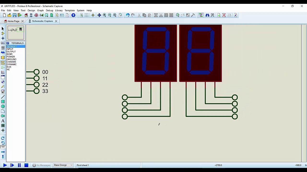
Circuit 74LS192 partie 2 - YouTube

74LS192