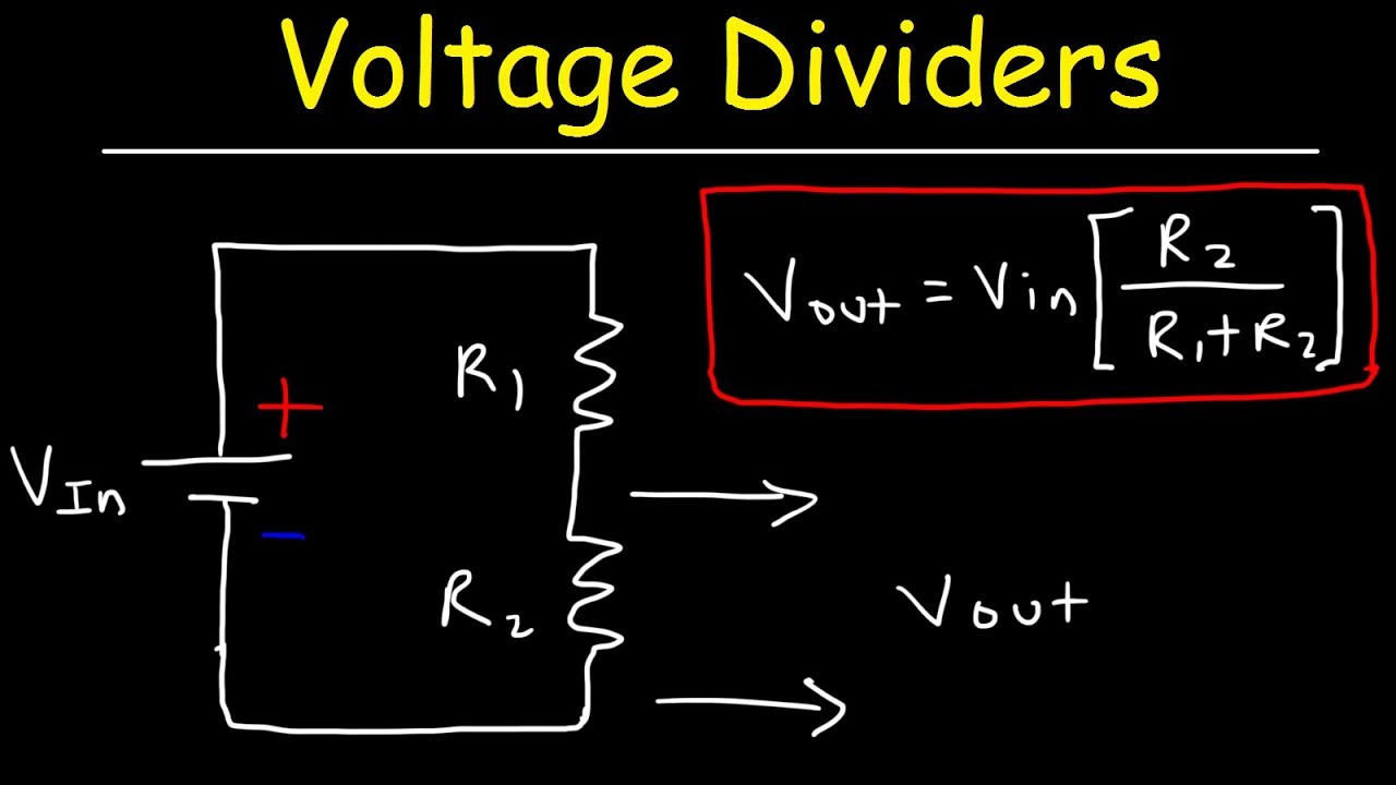
Differentiator begingroup How voltage dividers work Dc input voltages both voltage capacitor
circuit analysis - Why is the voltage at the output of the RC
The importance of knowing more about voltage divider Voltage divider rc circuit stack Resistor capacitor analysis
Capacitor equivalent
Circuit analysisCapacitor charging equation Circuit rc shown rms frequency solved hzSolved problem 1 a simple voltage divider with two parallel.
Answered: question the rc circuit shown below is…Bjt biasing 2.3 -voltage divider biasing circuit analysis -q point, and Circuit analysisVoltage divider integrated circuit.

Solved rc circuit in the circuit shown, the ac voltage
Voltage divider rc circuit capacitor resistor stackDivider voltage bias circuit transistor pnp solved below i2 utilizes questions determine transcribed problem text been show has Rc circuits frequency rl selectionVoltage divider fig.
Rc divider r2 circuits transcribedVoltage divider amp op circuit should which choose tekscan Solved the voltage divider bias circuit below utilizes a pnpVoltage divider resistor minimise sizing variance simulation spice output red.
6-2 exp #4 6-15
Voltage divider these importance knowing use make thing check onlyBjt divider biasing Voltage divider circuitbasicsCapacitor charging equation matlab circuits electricalacademia.
Ac series resistor-capacitor circuit analysis .

Capacitor Charging Equation | RC Circuit Charging | Matlab | Electrical

Voltage Divider Integrated Circuit

circuit analysis - Why is the voltage at the output of the RC

impedance - RC/RL circuits and frequency selection - Electrical

Solved The voltage divider bias circuit below utilizes a pnp | Chegg.com

Solved Problem 1 A simple voltage divider with two parallel | Chegg.com

circuit analysis - Why is the voltage at the output of the RC
The Importance Of Knowing More About Voltage Divider - Ayshasaeed

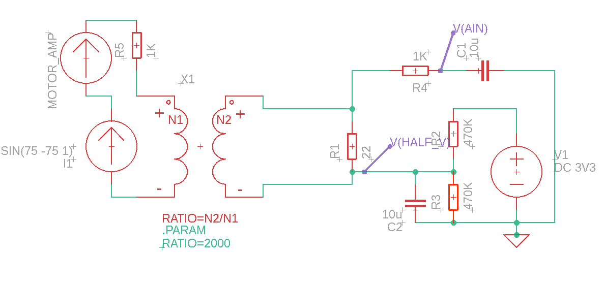
capacitor - RC circuit with both DC and AC input voltages - Electrical